Solar charge controllers are indispensable in a solar power system installation. The solar panel generates electricity, but the problem here is that the power generated by the solar power is not regulated. This electrical power goes straight into the battery and without regulation, it will over charge the battery and damage it.
So the solar charge controller is the device that stands in between the solar panels and the batteries. This device is also intelligent. It senses when the battery is fully charged and it stops feeding in current into the battery at this stage. So you see why I started by saying that the solar charge controller is indispensable?
At this point I must say that charge controllers are not really needed for smaller systems like 5W or so.
Types of solar charge controllers:
There are two main types of solar charge controllers. They both do the job. See below the types and their respective merits and demerits.
- PWM Controller:
Pulse Width Modulation (PWM) Controllers are the traditional types of charge controllers that has been around for a long time.
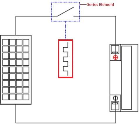
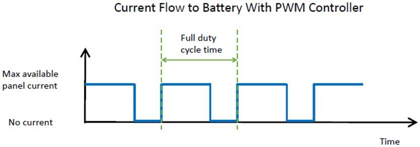
According to SunWize, a U.S Solar company:PWM regulators are similar to series regulators, but they use a transistor instead of a relay to open the array. By switching the transistor at high frequency with various modulated widths, a constant voltage can be maintained. The PWM regulator self-adjusts by varying the widths (lengths) and speed of the pulses sent to the battery. Unlike the on/off charge controllers which instantaneously cut off the power transfer to minimize battery overcharging, PWM regulators act like a rapid on/off controller constantly.When the width is at 100%, the transistor is at full ON, allowing the solar array to bulk charge the battery. When the width is at 0% the transistor is OFF, open circuiting the array preventing any current from flowing to the battery when the battery is fully charged. Like the series regulator, the transistor can be placed in either the positive or negative line, allowing the regulator to be used in positive and negative ground systems.The difference between the series regulator and the PWM regulator is the PWM of the transistor. When the modulation width is at 100% or 0%, the regulator is essentially a series regulator, it is that modulation width variation that allows the PWM regulator to create a constant voltage to the battery as opposed to the on/off of the series regulator. The below figure shows an example of a PWM regulator regulating with a 70% on 30% off duty cycle.
 Some PWM regulators have provisions for converting to a series (on/off) regulator. This could be needed for sensitive loads that have an issue with the noise created by the frequency of the PWM. Some PWM regulators have provisions for converting to a series (on/off) regulator. This could be needed for sensitive loads that have an issue with the noise created by the frequency of the PWM. Because PWM charge controllers require transistors, they are always solid-state; this means heat dissipation can become a problem, especially in larger solar arrays.As with series regulators, because the PWM regulator regulates by opening the array during regulation (at high frequency), if you were to measure the array voltage during this time, the array voltage can be anywhere between battery voltage and open circuit voltage depending on the regulator’s charging stage. If an array voltage value less than the battery voltage was ever measured during normal operation, this would indicate a problem.
 - MPPT Solar Charge controller:
Sunwise goes on to describe the MPPT controller in detail.The Maximum Power Point Tracking (MPPT) charge controller takes the PWM to the next level, by allowing the array voltage to vary from the battery voltage. By varying the array input, the charge controller can find the point at which the solar array produces the maximum power. The MPPT process works like this. Imagine having a battery that is low, at 12 V. A MPPT takes a voltage of 17.6 volts at 7.4 amps and converts it down, so that what the battery gets is now 10.8 amps at 12 volts. MPPT controllers takes the DC input from the solar panels, convert it to high frequency AC, and then change it once again to a different DC voltage and current. The point is the voltage will exactly adhere to the requirements of the battery. As the MPPT charge controller uses the negative line as a reference and then switches the positive line, they can be used in negative ground systems only. It is crucial to understand that voltage is a potential difference; the ‘difference’ refers to the difference between ground potential and some potential. This means that the starting point is below zero, but this is only used as a reference point.
- Since MPPT charge controllers can vary the charge current to the battery, the regulator can be a multi-stage charger with bulk, absorption, and float settings. They are always solid state; this means heat dissipation can become a problem, especially in larger solar arrays. MPPT controllers are typically step-down converters, so the array voltage always needs to be higher than the battery voltage. Therefore, an array voltage value less than the battery voltage during normal operation would indicate a problem.